The main objectives of this project is to create an experimental mass-spring-damper platform, along with its demonstration videos, to help UBC MECH 463 mechanical vibration course students to efficiently grasp the concepts of multi-body dynamics. The resultant platform has a modular design consists of two carts constrained to perform linear movement and multiple sets of springs and weights used to tune the physical parameter of the carts. An AC brushless motor is used to provide force input to the cart (the system is technically a 3 DOF system, considering the rotor’s moment of inertia) and sensors are implemented to collect carts’ movement information. The platform is of course configurable between 1 DOF and 2 DOF cases. I then programmed an automated frequency response function (FRF) collection routine using MATLAB codes and implemented it to both 1 DOF and 2 DOF systems through a National Instrument’s DAQ unit. In short, the routine performs sine sweep (step-wise) for a range of specified frequencies, measures the cart’s amplitude response at those frequencies, and automatically update the computer screen to create a FRF plot.
Mass-Spring-Damper Platform
On the platform surface, each cart is supported by 4 bearings. At the bottom of each cart, there are also horizontally mounted bearings located at the slots and the bottom surface of the platform. These hidden bearings constrain the carts so that they can only perform linear motion. Limit switches are also mounted at both sides of each cart to cut the actuator power in case the cart displacement goes extreme.
1 DOF Mass-Spring-Damper
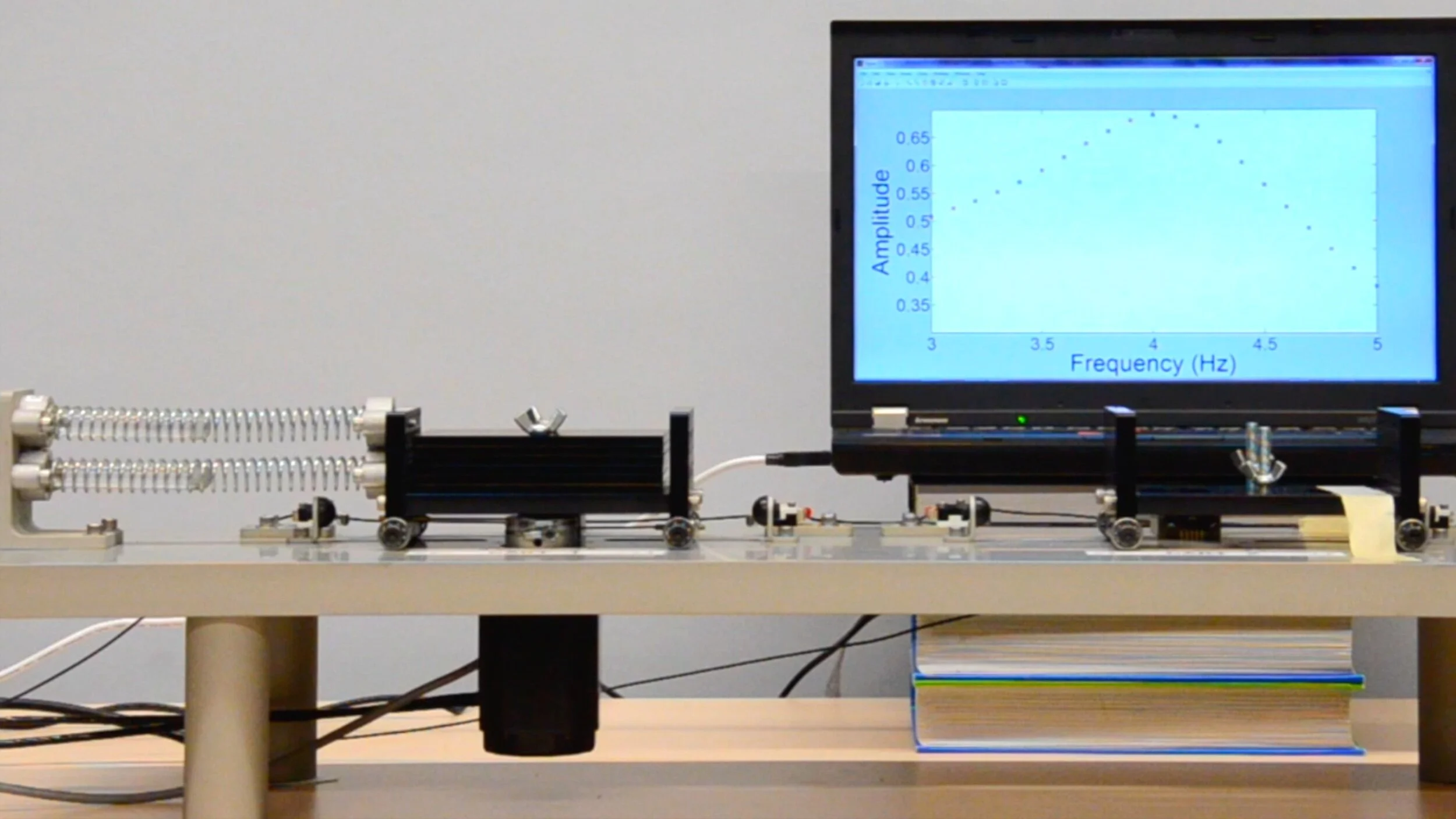
In the 1 degree of freedom configuration, cart 1 on the left is connected to the platform frame by two springs and is excited by an actuator. Cart 2 on the right is unused and taped down to the platform. Frequency response of cart 1 from 3 Hz to 5 Hz is obtained.
< Click image to play video >
2 DOF Mass-Spring-Damper
In the 2 degrees of freedom configuration, cart 1 maintains the same configuration as the 1 DOF case. Cart 2 on the right is connected to cart 1 through a metal spring (all three springs are of identical specs), and cart 2 is roughly tuned to have the same natural frequency as cart 1. Amplitude measurement is taken from cart 1. Frequency response is acquired from 1.5 Hz to 6.5 Hz. Note the video was edited to start around the 2.3 Hz measurement.
< Click image to play video >
The figure shows cart 1’s frequency response function in 1 DOF and 2 DOF mass-spring-damper systems. The 1 DOF case shows 1 amplitude peak at its resonance frequency. The 2 DOF case shows two resonance frequencies, and both are different from the resonance frequency of the 1 DOF case. In the 2 DOF case, cart 2 acts like a vibration absorber which almost completely attenuates cart 1’s movement around 3.1 Hz.
Experimental Setups

Equivalent system parameters for 1 DOF system were identified for different spring and weight configurations using periodic decrement technique. The spring configuration that showed the least equivalent damping was chosen for the demonstration so that the amplitude at the resonance frequency is more apparent to the viewers.

The steel cable drive connected to cart 1 (left) was coupled to an AC brushless motor who’s driver was set to torque control mode. Carts’ position signals were sensed by linear optical encoders. The encoder quadrature signals were then converted to analogue position values using digital-analog converters.