Unicompartmental knee arthroplasty (UKA) is an orthopedic surgery where a surgeon cuts away arthritic knee articulating surfaces and installs artificial implants there to restore knee function. Compared to other knee arthritis treatment methods, UKA is technically demanding and has higher risk of revision surgery. In order to lower this risk, I developed a robotic device to assist surgeon in performing the UKA bone cutting with improved accuracy and consistency. During an operation, the robot is mounted to the patient’s femur so that the robot base maintains its relative position with respect to the bone. The robot then mechanically and dynamically defines the depth of cut that the surgeon can make on the bone at any given moment based on the 3D surface geometry (virtual fixture) saved in its memory. I tested the robot and validated its capability of achieving high accuracy and consistency in the bone cutting procedure. The quantified performances are comparable or better than the other commercialized UKA robotic systems. Also see the accuracy validation project page for more details.
OMKnee:
Bone-Mounted UKA Robot
OMKnee UKA robot lets users utilize human dexterity while augmenting the action by imposing virtual fixture in high accuracy.

3 Degrees of Freedom Robot Joint Configuration
The robot has a rotary-prismatic-prismatic joint configuration, which forms a cylindrical workspace that completely encloses the medial femoral condyle. All the joints are pre-loaded to eliminate backlash. Within the workspace and away from the virtual fixture surface, users can freely maneuver the milling burr.
< Click image to play animation >
Remote Centre of Motion Milling Tool Holder
For an assistive robot, ergonomics is a key to its success. I thus developed a remote centre of motion (RCM) mechanism to mount the milling tool to the main robot structure. The mechanism allows the milling tool to tilt while maintaining the burr’s spatial position (both RCM joints are also pre-loaded). Thereby, users can freely alter holding posture and maneuver the burr into tight space without colliding with soft tissue.
< Click image to play animation >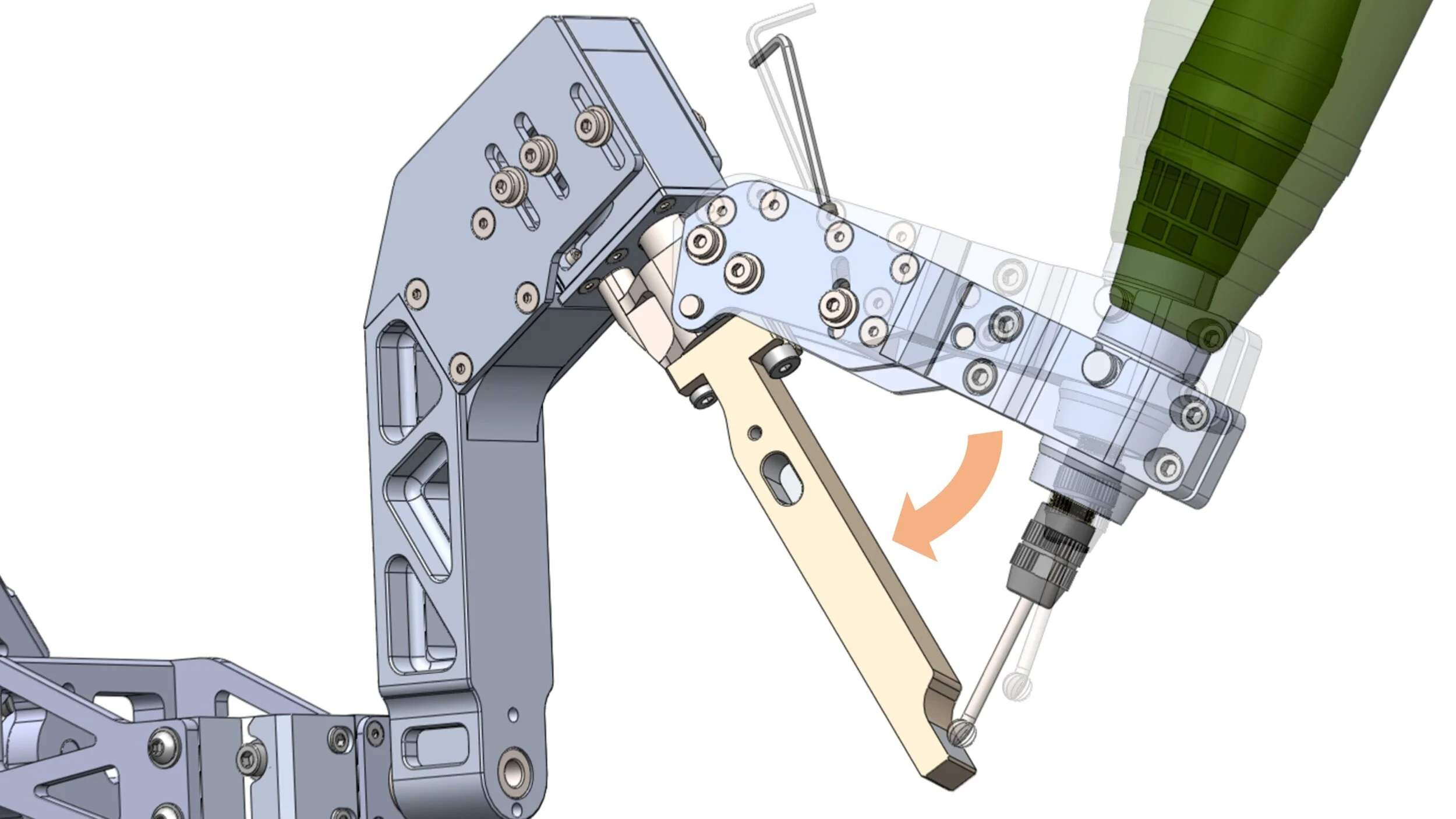
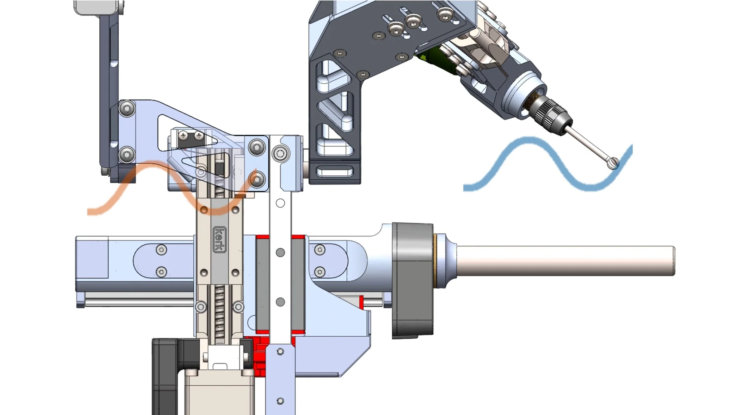
The RCM mechanism has a built-in fine-adjustment feature that facilitates re-tuning of the alignment between burr centre and two RCM rotary axes.
< Click image to play animation >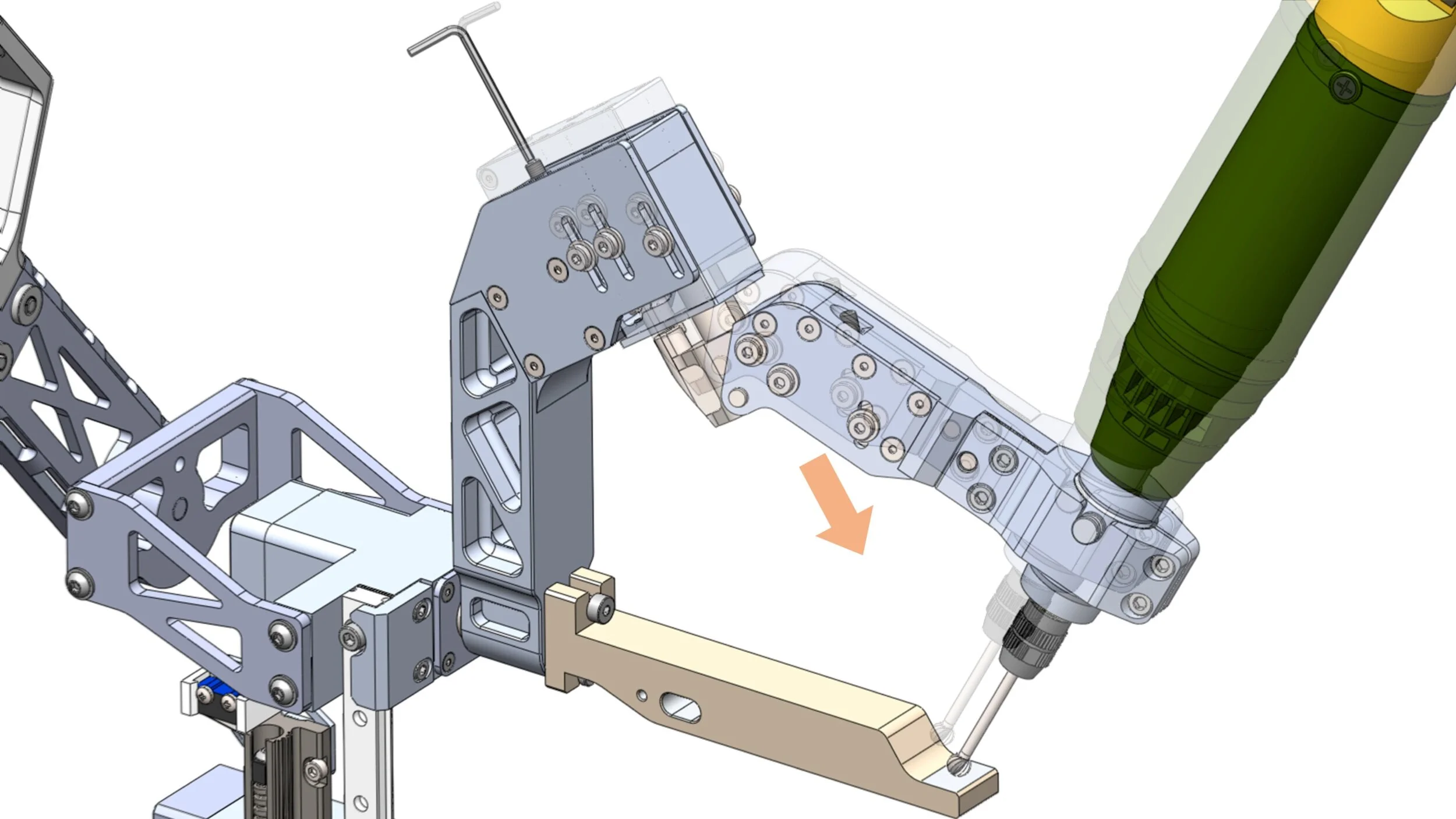
With custom tuning jigs, re-tuning of each axis can be performed individually. The adjustment feature also enables RCM to accommodate different burr diameters.
< Click image to play animation >
Meticulous Attention to Detail is Given to all Components
Without including off-the-shelf parts, the robot consists of more than 40 custom-made components. In addition to fulfilling all functional requirements, I designed these components with assembly error reduction and ease of maintenance in mind. Their fully specified mechanical drawings facilitated smooth communication with professional machinists who did fantastic jobs realizing my design.
Dynamic Physical Constraint
At the heart of the OMKnee robot, there lies a linear blocker which dynamically and physically limits the lowest reachable milling depth as defined by the virtual fixture geometry, hence the name dynamic physical constraint (DPC). As users maneuver the robot joints, joint encoders send position information to microcontroller, which use the information to search its internal memory and calculates required blocker movement to reach proper radial blocking position within the robot’s cylindrical work space.
Real-Time Hard Boundary Contact Emulation
DPC is driven by an anti-backlash lead screw coupled to a stepper motor. The mechanism is not back-drivable and is capable of moving at 25mm/s even under a load of 50N. Therefore, DPC can emulate the sensation of contact with a hard surface. The overall actuation is closed-loop, as the microcontroller reads real-time blocker position from an rotary encoder equipped at the motor and adjusts the command signal accordingly.
< Click image to play animation >
Custom-Designed Enclosure Houses all Electronics
I designed a robust control box enclosure to contain all the electronics needed for robot control. The enclosure is also equipped with an intuitive user interface at its front panel for robot initialization and manual driving of the DPC blocker. The connector, control, and warning labels are directly printed to the panel surfaces for clarity.
[ Enclosure fabrication sponsored by PROTOCASE ]

Component placement is carefully planned with heat dissipation and EMI reduction in mind. They are mounted to the enclosure via self-clinching nuts. Some space is left for accessibility and potential upgrade in the future.

I designed 4-layer printed circuit boards using EAGLE PCB CAD to interface sensors and motor driver with the microcontroller. Note cyan (power) and yellow (ground) patterns are turned into filled layers on the actual boards.
Virtual Fixture Creation and Conversion

Research of UKA femoral implant-to-bone interface geometries led to my testing of tri-planar type and combined-curved type geometries, which are the most common in the market. An example of tri-planar type is shown here.

In Siemens NX CAD environment, I created virtual fixture surface using freeform surface modelling technique. The virtual fixture not only defines the implant-to-bone interface geometry but has additional coverage to ensure smooth transition in and out of the milling zone.

The CAD-generated virtual fixture surface is imported to MATLAB environment, where it is sampled and converted into a geometry data lookup table compatible to the microcontroller. The conversion factors in robot’s sensor and actuator parameters and the burr offset.
Device Transportation Solution

OMKnee robot’s main unit and its accessories (calibration jigs, initialization tools, replacement burrs, alternative handle part, etc.) are stored in a water-proof and shock-proof Pelican case with custom-cut foam.

The robot’s control box and validation rigs are also stored in a Pelican case. These cases allow safe transportation of the entire experimental setup for robot demonstration at various occasions.